Summary
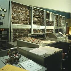
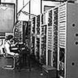
The test unit was used to check CSIRAC while it was in operation. The tests were not on a micro level but more for routine maintenance and to check that the different components were working well and together.
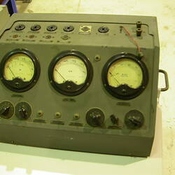
The test unit consists of a rack of chassis (circuit boards) and is mobile.
(A rack is a metal frame into which modular components (chasses) were bolted. The standard width was 19 inch.)
The test unit was constructed by the CSIRO Division of Radiophysics, according to a standard design. It was a general purpose workhorse for testing any of the components of CSIRAC, for example, input and output circuits, arithmetic unit, memory or the drum circuitry.
There were three test units used to check CSIRAC; all were used independently of each other. This one and the test unit Registration Number 044255 were similar in that they were for general purposes.
The date range (1949-1964) is given to indicate that changes were made to structure and circuitry over the period of CSIRAC's working life.
There are eight chasses in this rack. (They are numbered here only for the sake of clarity):
Chassis Number One (the top chassis) is a special time base generator, which generates time base signals appropriate for CSIRAC; it has pre-set timings.
Chassis Number Two (below Chassis Number One) holds two cathode ray oscilloscopes (CRO) and their controls. They were standard CSIRO Division of Radiophysics equipment. The CRO, on the right side, was a dual beam long persistence tube; the CRO on the left was a single beam. The oscilloscopes were used to monitor pulses to check timing of CSIRAC. All the pulses had a precise relationship to each other. The timing between different pulses had to be set up and/or checked.
Chassis Number Three (below Chassis Number Two) is a time base and delay generator for producing the horizontal 'axis on the CRO screen; also standard CSIRO Division of Radiophysics equipment.
Chassis Number Four (below Chassis Number Three) includes a vacuum tube voltmeter with a very high input impedance so it does not affect the voltages it is measuring; also standard CSIRO Division of Radiophysics equipment.
Chassis Number Five (below Chassis Number Four) is a cathode follower probe (CF). A CF is a triode valve, which prevents distortion and loading of the signal being observed. It is used with the CROs and the vacuum tube voltmeter. It is standard CSIRO Division of Radiophysics equipment.
Chassis Number Six (below Chassis Number Five) is a camera control unit for taking images of the CRO screens. There was an attachment for a Polaroid camera on the double beam oscilloscope (Chassis Two)
Chassis Number Seven (below Chassis Number Six) is a power supply unit.
Chassis Number Eight (below Chassis Number Seven) is a power supply unit.
Physical Description
Rectangular metal cabinet with no rear cover and front with several chassis panels. A probe is connected to asocket in chassis # 4. It is tucked into a pigeon hole together with other loose cables.
More Information
-
Collection Names
-
Collecting Areas
-
Acquisition Information
Donation from Commonwealth Scientific & Industrial Research Organisation (CSIRO), Frank Hirst - University of Melbourne (The), Mar 1965
-
Designer
-
Designer
-
Commissioned By
Commonwealth Scientific & Industrial Research Organisation (CSIRO), Sydney, Greater Sydney, New South Wales, Australia, 1949-1955
-
User
-
Inscriptions
Chassis Number Five (below Chassis Number Four): Type U1155 Chassis Number Six (below Chassis Number Five): Type RPL Unit U1154 Note: 'RPL' = Radio Physics Laboratory
-
Classification
Computing & calculating, Digital computing, Testing equipment
-
Category
-
Discipline
-
Type of item
-
Overall Dimensions
690 mm (Width), 510 mm (Depth), 1870 mm (Height), 191.5 kg (Weight)
-
Exhibition Collection Management
510 mm (Length), 690 mm (Width), 1870 mm (Height)
-
References
CSIRO Science Image No. 2923 (Nov 5, 1952) - shows Trevor Percey sitting beside this test unit albeit with an extra chassis on top. MM 90899.31, Photograph - CSIRAC Computer, Trevor Pearcey and CSIRAC, 21 September 1951
[Book] McCann, Doug & Thorne, Peter. 2000. The Last of the First CSIRAC: Australia's First Computer. 196., 2000
-
Keywords
Computers, Computing, CSIRAC (Computer), Making History - CSIRAC