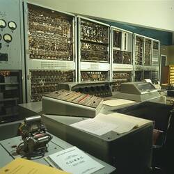
Summary
The test unit was used to check CSIRAC while it was in operation. The tests were not on a micro level but more for routine maintenance and to check that the different components were working well and together.
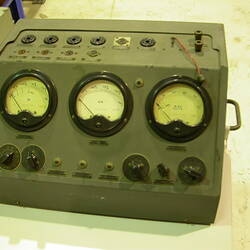
The test unit consists of a rack of chassis (corresponding to circuit boards in modern equipment) and is mobile.
(A rack is a metal frame into which modular components (chasses) were bolted. The standard width was 19 inch.)
The test unit was constructed by the CSIRO Division of Radiophysics, according to a standard design. It was a general purpose workhorse for testing any of the components of CSIRAC, for example, input and output circuits, arithmetic unit, memory or the drum circuitry.
There were three test units used to check CSIRAC; all were used independently of each other. This one and the test unit Registration Number 044254 were similar in that they were for general purposes.
The date range (1949-1964) is given to indicate that changes were made to structure and circuitry over the period of CSIRAC's working life.
There were four chasses in this rack numbered here only for the sake of clarity:
Chassis Number One (the top chassis ) holds two cathode ray oscilloscopes (CRO) and their controls. They were standard CSIRO division of Radiophysics equipment. The CRO, on the right side, is a dual beam long persistence tube; the CRO on the left was a single beam.
The oscilloscopes were used to monitor pulses to check timing of CSIRAC. All the pulses had a precise relationship to each other. The timing between different pulses had to be set up and/or checked.
Chassis Number Two (below Chassis Number One) was a timing and delay generator for producing the horizontal axis on the CRO screen; also standard CSIRO Division of Radiophysics equipment.
Chassis Number Three (below Chassis Number Two) was a high frequency (HF) oscillator. It was not part of the original Radiophysics test rack. Its use is uncertain; it may have been used to test the clock. This chassis includes valve in sockets. The sockets were inserted in holes punched out by a special tool that left a little tab on the inside rim to prevent rotation of the socket when the valve was being inserted or removed. This is a minor but nevertheless significant example of the high quality of the equipment built by the CSIRO Division of Radiophysics.
Chassis Number Four (at the bottom separated from Chassis Three by a large space) was the power supply unit. Power supplies being heavy, were always placed at the bottom for stability reasons.
More Information
-
Collection Names
-
Collecting Areas
-
Acquisition Information
Donation from Commonwealth Scientific & Industrial Research Organisation (CSIRO), Frank Hirst - University of Melbourne (The), Mar 1965
-
Designer
-
Designer
-
Commissioned By
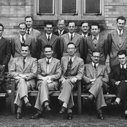
Commonwealth Scientific & Industrial Research Organisation (CSIRO), Sydney, Greater Sydney, New South Wales, Australia, 1949-1955
-
User
-
Inscriptions
Chassis Number One on the top (numbering only for the sake of clarity) RPL Type U1143 Chassis Number Two Type U1142
-
Classification
Computing & calculating, Digital computing, Testing equipment
-
Category
-
Discipline
-
Type of item
-
Overall Dimensions
690 mm (Width), 510 mm (Depth), 1870 mm (Height)
-
Keywords
Computers, Computing, CSIRAC (Computer), Making History - CSIRAC