Summary
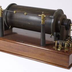
Tuner with built in crystal detectors and the facility to use a Fleming diode as an alternative detector. It operated on the 120-700 metre waveband. This type of receiver was used as a ground based receiver during the latter part of World War I, 1917-1918. It received information transmitted from spotting aircraft to assist in targetting of enemy positions.
Manufactured by the Automatic Telephone Manufacturing Company in 1918.
Physical Description
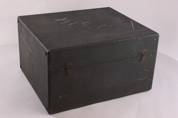
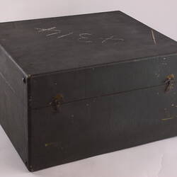
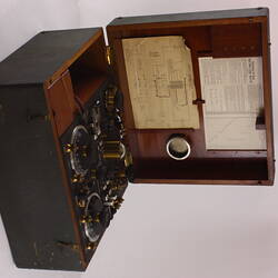
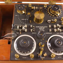
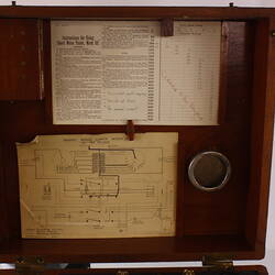
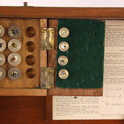
Rectangular greyish cloth covered wooden box with carrying handle and removable hinged lid. Opening the lid reveals a slate coloured panel with two rotary switches, two double pole knife switches, two tuning contols, a coupling control, a potentiometer control, a small knife switch, a push button, a Perikon detector with crystal in place, a carborundum dtector, eight brass terminals and four fling leads (two red and two black) fitted with spade terminals. There are two lidded compartments, one in the lid and one (broken) in the body. The compartment in the lid contains twelve mounted mineral crystals for use in the Perikon detector. There is a nickel plated circular fitting in the lid (for watch?), and wooden holders for cards. There are two instruction cards.
More Information
-
Collecting Areas
-
Acquisition Information
Donation from R. Mackay, 28 May 1960
-
Manufacturer
A.T.M. Co Ltd, Milton Road, Edge Lane, Liverpool, England, Great Britain, 1918
See References. November 1911: Automatic Telephone Manufacturing Company founded. 1916 Produced the Mk II Tuner crystal set used by Royal Flying Corps. 1918 Produced the Aircraft Receiver Mk III, a 3-valve model -
Inscriptions
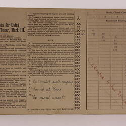
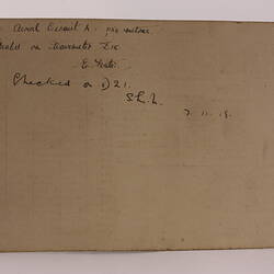
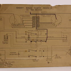
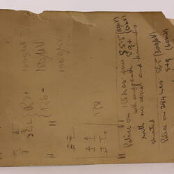
Outside top of box: (chalk) 4314 Embossed both on hinge sides of lid and of box: 68 Panel: (between 2 knife switches) SHORT WAVE TUNER / MARK.III* / No. 4314 / A.T.M. Co. Ltd. / 1918 / (text) Panel: (terminals) A E / VALVE / TEL.1. / TEL.1. / TEL. 2. / TEL.2. / (flying lead terminating block) + / DETr. / - / - / BUZr. / + Panel controls: C.C.I. (closed circuit inductance) / A.T.I. (aerial tuning inductance) / COUPLING / TUNE / STAND BY / CARBORUNDUM / VALVE / PERIKON / POTR. / LOCK / BZR.KEY / OFF BATTERY ON / C.C.C. (closed circuit condenser) / A.T.C. (aerial tuning condenser) Card # 1: Instructions for Using Short Wave Tuner, Mark III* / (printed text) / (handwritten text) / (tuning table covering (wavelength) 50 to 700 Rear of Card #1: (handwriting) / (text) / E. Foster / (text) / 7 11 18 Card # 2: SHORT WAVE TUNER MARK III / 100 - 700 METRES / (schematic with labels) / (handwritten) No 4292 Rear of Card # 2: (handwritten text) / 3GL / (text) / 3UZ / (text) / Police on 1.68 mcs / (text) Luggage tag on carrying handle: (handwritten) SHORT WAVE / TUNER / MARK III / 1918 / 24831
-
Classification
-
Category
-
Discipline
-
Type of item
-
Overall Dimensions
350 mm (Width), 300 mm (Depth), 200 mm (Height)
-
References
1. Grace's Guide. Accessed 13 December 2012. [Link 1] 2. Antique Radio Classified. Accessed 12 December 2012. [Link 2] 3. EARLY AND UNUSUAL RADIO APPARATUS AND HISTORY. Accessed 12 December 2012. [Link 3] 4. UK TELEPHONE HISTORY. Accessed 12 December 2012. [Link 4] 5. FROM STROWGER TO SYSTEM X. Accessed 13 December 2012. [Link 5] 6. Australian War Memorial. Accessed 18 December 2012. [Link 6] 7. Imperial War Museum. Accessed 18 December 2012. [Link 7]
[Book] COURSEY, P. R. 1922. Radio Experimenters Handbook., 1922, 45-50 Pages
-
Keywords