World War 1 created an impetus for the rapid development of radio technology by both sides in the conflict.
The years between 1914 and 1920 saw the electronic valve change rapidly from a primitive, but useful, detector to a device that could be used for amplification and oscillation. Amplification, of audio and radio frequency signals, vastly increased the sensitivity of radio receivers. Transmitting valves were also developed, which could produce clean continuous wave radio frequency power, a great improvement on the damped wave trains characteristic of spark transmitters. These developments paved the way for wireless telephony.
Museum Victoria's Collection has a number of objects from this period:
- Crystal receiver for messages from aircraft in WW 1 (ST 024861)
- Early valve receiver (ST 015460)
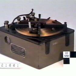
- Airborne spark transmitter, representative of the airborne radio technology during the war. Valve based transmitters were manufactured near the end of the War but, even so, were too heavy and complex. Receivers using one valve were used in aircraft (ST 021661)
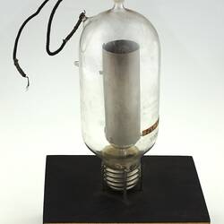
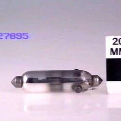
- English valves: ST 019833, ST 022703, ST 027895
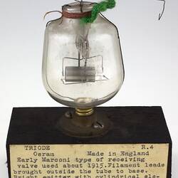
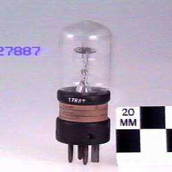
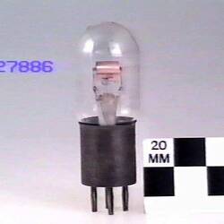
- German valves: ST 027887, ST 027886
- Valve from USA: ST 027901
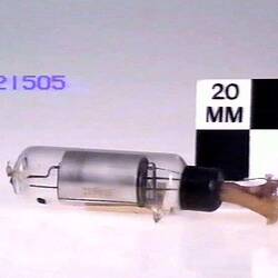
- Australian valve: ST 21505
The following lists some collection items that illustrate the transmission and receiving processes for this period
The transmission process
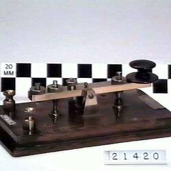
Stage 1: A morse code signal is keyed in
ST 21420, Morse Key - AWA, Radio, 1915-1920
Stage 2: The spark from the induction coil produces radio frequency in a suitable tuned circuit, consisting of a coil and the main capacitor
ST 015466, Induction Coil - AWA, Marconi Ship Radio, 1918
ST 021421, Induction Coil - AWA, Telmar, Emergency, 1914-1920
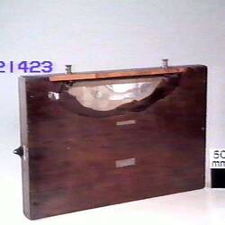
ST 021423, Capacitor - AWA, Spark Suppressor, 1915-1920
Stage 3: A coil isolates the spark coil from the transmitting tuned circuit
ST 021413, Coil - AWA, High Frequency Inductance, 1914-1920
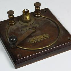
Stage 4: A tune indicator is used to adjust aerial tuning inductance for a maximum transmitting power.
ST 021422, Tune Indicator - AWA, Spark Transmitter, 1914-1920
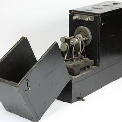
Transmitters in aircraft
In an aircraft spark transmitter, the induction coil, spark gap and tuned circuit were integrated into a compact package suitable for aircraft.
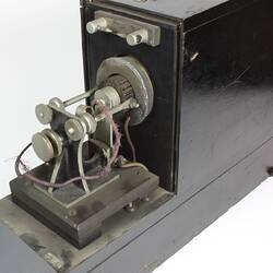
ST 021661, Aircraft Spark Transmitter - Wireless Transmitter No.1, circa 1918
The receiving process
Receivers used detectors to rectify the incoming signal
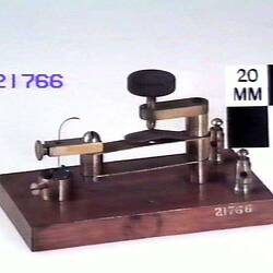
ST 021766, Crystal Detector - Unknown Maker, Variable, circa 1916
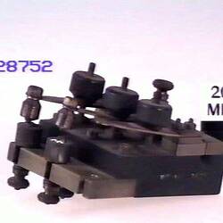
ST 028752, Crystal Detector - Three Leafs, Radio Receiver, circa 1918
ST 015019, Detector - Unknown Manufacturer, Radio Receiver, 1906-1923
The following are complete receivers, needing just an aerial, batteries and headphones.
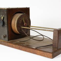
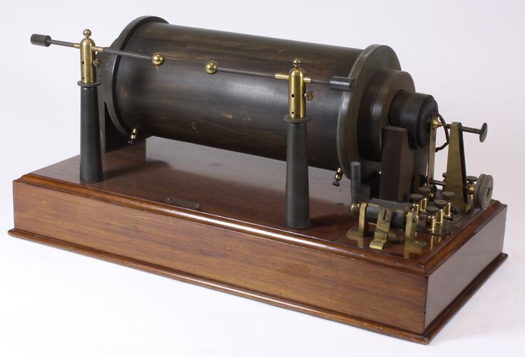
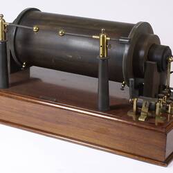
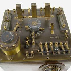
ST 021424, Radio Receiver (valve)
ST 015460, Radio receiver (valve)
ST 024861, Crystal Set
HT 26360, Loose Coupler
For better selectivity, many crystal receivers used two tuned circuits, one to tune the aerial and the other to tune the detector circuit. A common realisation of this approach was the Loose Coupler (HT 26360). The outer winding was connected to the aerial and was tuned by adjusting the taps on the coil; the inner winding was connected to the detector and was tuned by a variable capacitor (not part of this object) and by varying the taps. Coupling between the two windings was varied by sliding the inner coil out from the outer one. Tight coupling (inner coil right in) gives good sensitivity but poor selectivity, loose coupling (inner coil moved out from the outer coil) gives lower sensitivity but god selectivity. The coupling is adjusted to give the best compromise on the station required. The radio receiver (ST 024861) used two separate tuned circuits with variable coupling between them to achieve similar performance..
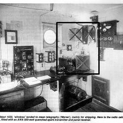
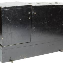
Ship Power
On ships, a switchboard was used to control and measure the power to the equipment.
ST 021404, Switchboard - AWA, Spark Transmitter, circa 1920
More Information
-
Keywords
-
Authors
-
Article types