Summary
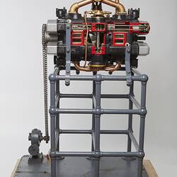
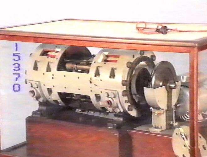
Reputed to be the first prototype crankless air compressor built by Crankless Engines (Australia) Pty Ltd. The machine was acquired by the Science Museum of Victoria directly from the Melbourne-based company in June 1924 and subsequently sectioned for display.
The crankless air compressor utilises a tilted swash plate (referred to as a 'slant' by the inventor), in place of a conventional crankshaft, to transfer rotary motion from the central drive shaft into reciprocating motion of the pistons. The design was based on the principles outlined in Anthony George Maldon Michell's Australian Patent No.4627, for "Improvements in Mechanism for the Interconversion of Reciprocating and Rotary Motion", with detailed design work undertaken by a small team of draughtsmen employed by Crankless Engines (Aust.) Pty Ltd, under the supervision of Thomas Louis Sherman, an experienced automotive engineer, who worked as Michell's senior design collaborator from 1920.
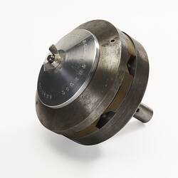
The machine is double-ended, having four cylinders at each end equally spaced around the shaft, with the axis of each pair of cylinders being parallel to the shaft. Working in the cylinders are four pairs of single-acting pistons, arranged on either side of the swash plate, with each pair rigidly connected by a central yoke straddling the swash plate. Thus, the forward 'working' stroke of each piston effects the return stroke of its pair. Power is transmitted from the swash plate to the pistons through pivoting bronze slippers, each of which has a hemispherical boss on the back nesting in a cup on the piston. The bosses are slightly offset so as the swashplate moves the slippers tilt slighting, creating a wedge-shaped film of lubricating oil between the sliding surfaces minimising friction, similar to the principle of the tilting pads in Michell's original thrust bearing invention of 1905.
The machine underwent extensive tests in the company's workshop at 129-131 Greeves Street, Fitzroy, coupled to a 14 horsepower direct current (D.C.) electric motor. It was described in an article that appeared in the British journal 'Engineering' of 5th Oct 1923, in which capacity was described as being 80 cubic feet of air per minute at a pressure of 100 pounds per square inch, when running at 750 revolutions per minute. According to this article, the compressor was built for consideration by the Victorian Railways to be used for supplying compressed air to operate Westinghouse type brakes on suburban electric trains. According to S.E.A. Walker two prototypes were built (assigned Machine Nos.2 & 3), but there is no record of it actually being adopted by the Railways.
The original display label (ST 015370.2) states that this unit was originally constructed as a single-stage compressor, but then later modified as part of experiments into a multi-stage arrangement, and remains in this configuration. It records the operating capacity as 100 cubic feet/minute at 100 p.s.i., when running at 1300 r.p.m..
Physical Description
Specifications: Number of Cylinders: 8 (multi-stage); Bore: 2.75 inches (69.85 mm); Stroke: 2.875 inches (73.025 mm); Operating Speed: 750 r.p.m.; Capacity: 80 cubic feet/minute at 100 p.s.i. (1699 litres at 689 kPa).
More Information
-
Collection Names
A.G.M. Michell Engineering Collection, Crankless Engines Collection
-
Collecting Areas
-
Acquisition Information
Purchase
-
Manufacturer
Crankless Engines (Australia) Pty Ltd, Melbourne, Greater Melbourne, Victoria, Australia, 1921
Crankless Engines (Aust.) Pty Ltd was registered as a private company on 24th August 1920, with a capital of £6,000 in £1 shares. The firm converted to a public company Crankless Engines Ltd. in 1924. -
Place & Date Made
-
Inventor
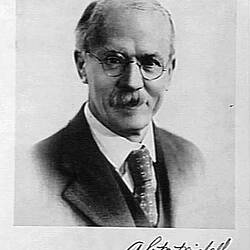
Mr Anthony G. Michell, Melbourne, Greater Melbourne, Victoria, Australia, 1917
The design was based on A.G.M. Michell's Aust. Pat. No.4627, for "Improvements in Mechanism for the Interconversion of Reciprocating and Rotary Motion". -
Designer
Mr Thomas L. Sherman - Crankles Engines (Aust.) Pty Ltd, Melbourne, Victoria, Australia, circa 1921
T.L. Sherman worked closely with A.G.M. Michell on the detailed design of the early machines made by Crankless Engines (Aust.) Pty Ltd. Under the title Chief Engineer, he was initially responsible for managing both the firm's design design office and workshop. -
Brand Names
-
Classification
-
Category
-
Discipline
-
Type of item
-
Overall Dimensions
227 kg (Weight)
Original weight of the complete compressor was recorded as 500 lbs (227 kg).
-
References
[Article] Cherry, T. M. 1962. Anthony George Maldon Mitchell, 1870-1959. Bio Memoirs of Royal Soc. No.8, 1962, pp.90-103 Pages
[Manuscript] Walker, Sydney E. Modest Man of Genius: An Account of Anthony Geroge Maldon Michell and The Crankless Engine., 1972 [updated Oct 1976]
[Book] Phillip, Stephen. 2020. What Came out of the Box: A Biography of AGM Michell.
-
Keywords
Air Compressors, Industrial Design, Innovation & Design, Inventions, Mechanical Engineering, Pneumatic Equipment