Summary
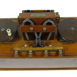
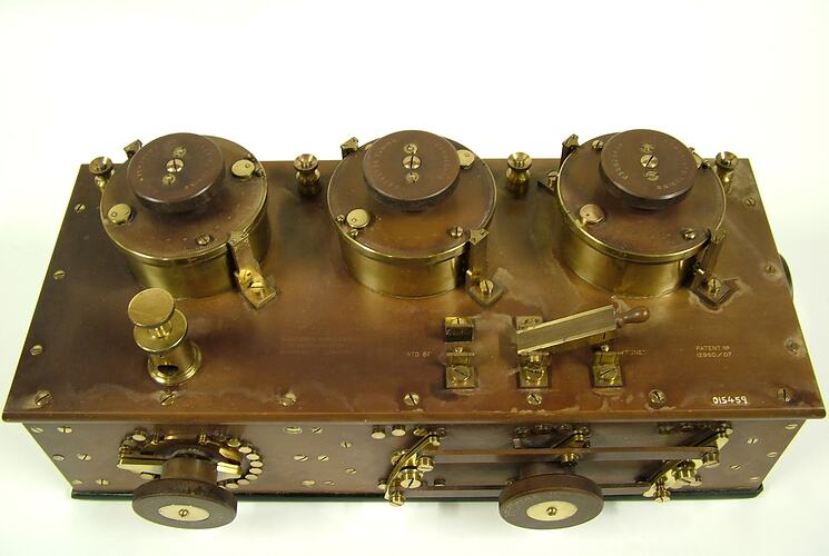
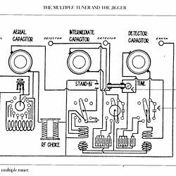
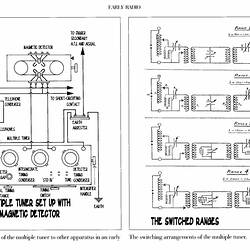
Multiple radio tuner, made by Marconi's Wireless Telegraph Company, England, circa 1908. Used with spark receivers on both land and sea. The tuner was connected between the aerial and the detector in order to select the receiving frequency. This type of technology was superseded during World war I (1914 - 1918).
This equipment is the same model as that used on the radio system on the Titanic ship at the time of the disaster in 1912.
Three controls on the top adjust the tuning of the aerial, detector and intermediate tuned circuits; the controls are variable capacitors. On the front, the left hand control adjusts the aerial tuning inductance and the right hand control perates three ganged switches, which set the tuning range of the three controls on top. The knife switch on the top selects between standby and tuned modes.
The item on the left hand front corner is the micrometer spark gap. This was provided to bypass the radio frequency energy coming from the transmitter when the key was pressed. There was no mechanical transmit/receive switching apart from the back contact of the key which would short the headphones when the key was pressed. This allowed 'break-in' operation where the operator would be able to hear another station trying to break in during the sending of a message.
Physical Description
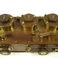
Wooden box with composition front panel and top. The top holds three large brass and composition controls, four terminals, one knife switch and a brass housing. The front panel holds one rotary switch and a three ganged switch. On one end is a rotary control.
Significance
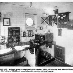
The equipment is typical of early shipboard radio in the period prior to the First World War (1914 - 1918); it is rare.
More Information
-
Collecting Areas
-
Acquisition Information
Donation from Amalgamated Wireless (Australasia) Ltd., 29 Dec 1924
-
Manufacturer
Marconi's Wireless Telegraph Co Ltd, London, England, Great Britain, circa 1908
-
Inscriptions
Engraved on top panel: MARCONI'S WIRELESS / TELEGRAPH Co Ltd / No 57835 LONDON / PATENT No 12960-07 Engraved next to terminals on top panel: AERIAL / DETECTOR / DETECTOR / EARTH Calibration on three controls on top panel: 0 1 2 ... 9 SHORT Knife switch on top panel: "STD BI" "TUNE" Knobs on top panel: AERIAL TUNING CONDENSER / DETECTOR TUNING CONDENSER / INTERMEDIATE TUNING CONDENSER Left hand knob on front panel: AERIAL TUNING INDUCTANCE / MICR-HENRIES / (scale) 0 6 25 60 110 180 270 370 500 665 840 1050 1270 1530 1820 2200 2600 3000 3400 4000 OFF Right hand knob on front panel: TUNING SWITCH / WAVELENGTHS / (scale in metres) 80 . . .(4 steps) . . . 2800 / (scale also in feet) Control on end: (scale) 0 10 20 30 . . . 90 Stamped on bottom of box: 57835
-
Brand Names
-
Classification
-
Category
-
Discipline
-
Type of item
-
Overall Dimensions
480 mm (Length), 230 mm (Width), 210 mm (Height)
-
Maximum dimensions
230 mm (Length), 482 mm (Width), 200 mm (Height)
Measurement From Conservation.
-
References
[Book] Jensen, Peter. 1994. In Marconi's Footsteps, 1894 - 1920., 1994, 100 Pages
-
Keywords