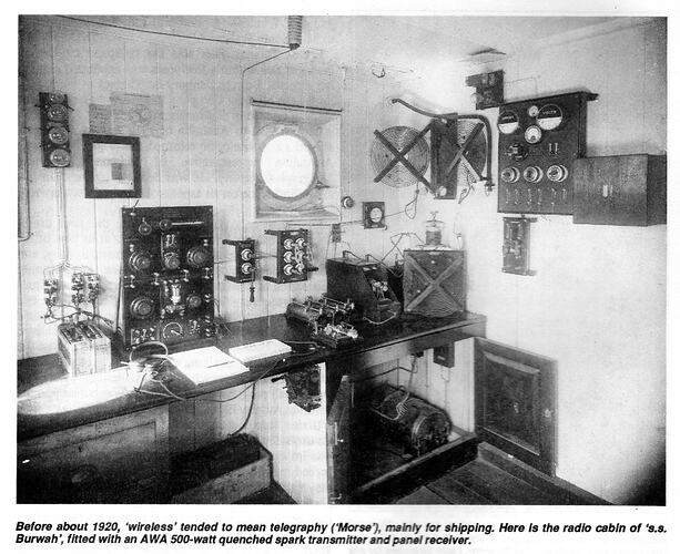
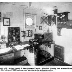
The period from 1900 to the beginning of the First World War saw the key events in the birth of radio as a communication technology. The following text briefly describes the transmission and receiving processes for this early period.
The Transmission Process
This process could involve high or low powered systems; the latter were used in emergencies.
High Powered System
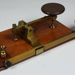
Stage 1: A morse code signal is keyed into the system.
Stage 2: High powered systems use alternating current at around 500 Hz from a rotary converter via a high voltage transformer to charge the main capacitor.
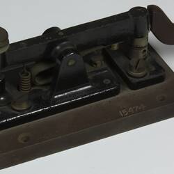
Stage 3: The signal then passes through a keying relay, which protects the morse operator (and the key) from the high voltages and currents required by the transmitter. The morse key could not stand up to the high energies involved in controlling the sparks.
Stage 4: A coil then maximises the transfer of energy from the alternating voltage source (the rotary converter) to the main capacitor.
Stage 5: The voltage is then stepped up to a high enough value to break down the spark gap using a transformer.
Stage 6: Choke coils isolate the spark circuit from the secondary of the transformer.
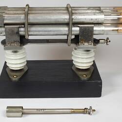
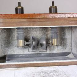
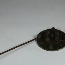
Stage 7: The signal in the form of the keyed high voltage developed on the main capacitor is discharged via a spark gap (discharger).
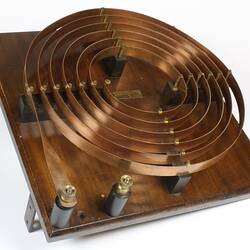
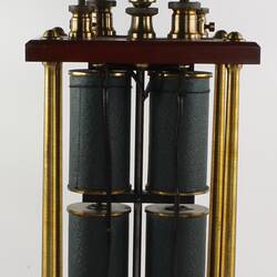
Stage 8: The energy in the main capacitor excites the oscillatory transformer to produce a damped oscillation at the resonant frequency.
Stage 9: The energy of the main oscillatory circuit is matched to aerial by the aerial tuning inductance.
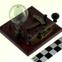
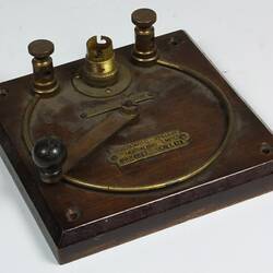
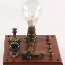
Stage 10: A tune indicator is used to allow the operator to adjust the aerial tuning inductance to maximise the radio frequency current in the aerial, indicated by maximum brightness of the lamp. In a typical ship's installation an earth arrestor is used to isolate the receiver from the transmitter during transmission, allowing the receiver to share the same aerial.
Low Powered System
A low powered system can work in two ways. In the earlier and simpler system, the spark coil is connected directly to the aerial, producing a broadband signal, which is likely to be picked up ships in the area regardless of the listening frequency. The second system, the tuned coil system, the spark coil is connected to the main capacitor and creates a spark across the existing discharger which excites the aerial in the normal way.
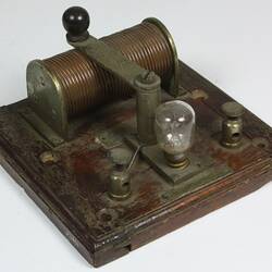
Low power or emergency transmitters use an induction coil as a high voltage source for the spark. They are controlled directly by the morse key. Capacitors are used across the interrupter of the induction coil to minimise sparking.
The Receiving Process
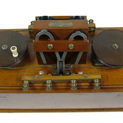
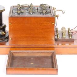
Stage 1: An incoming signal from an aerial passes through a multiple tuner, which selects the required receiving frequency. A multiple tuner has more than one tuning circuit. The multiple tuner contains a tapped inductor and variable capacitor to tune the aerial followed by two further tuned circuits to increase selectivity and to match the output to the low impedance of the signal coil of the magnetic detector with which the multiple tuner was designed to work.
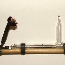
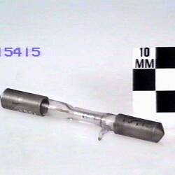
Stage 2: The output from the tuner is fed to a detector, which was initially a coherer, later to be replaced by a magnetic detector, crystal detector and thermionic valve.
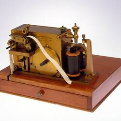
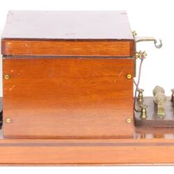
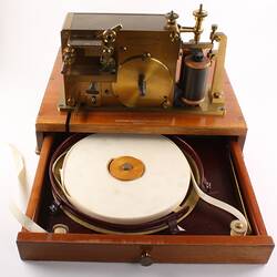
Stage 3: When a magnetic detector was used, its output was connected to earphones (known as telephones at the time). An adjustable capacitor, known as a telephone condenser, was placed across the output of the magnetic detector in parallel with earphones. The capacitor is adjusted to resonate with the inductance of the output circuit at the repetition frequency of the transmitter, making the signal easier to hear. Where a coherer was used, a morse inker could be used to produce a permanent record of the signal. Coherers were more suited to shore-based stations than ships.
More Information
-
Keywords
-
Authors
-
Article types